
What Is an HVLS Fan?
HVLS stands for High Volume, Low Speed — a class of large-diameter ceiling fans engineered to move massive quantities of air at very low rotational speeds, creating a broad, gentle column of airflow that covers entire facility floors.
High Volume Airflow
A single 7.3m HVLS fan can move over 25,000 m³ of air per hour — equivalent to running dozens of standard pedestal fans simultaneously.
Ultra-Low Energy Draw
Modern PMSM and BLDC motors draw 0.5–2.5 kW at full load. Compared to running multiple smaller fans or additional HVAC units, HVLS delivers a dramatically lower cost per cubic meter of air moved.
Ultra-Low Energy Draw
Modern PMSM and BLDC motors draw 0.5–2.5 kW at full load. Compared to running multiple smaller fans or additional HVAC units, HVLS delivers a dramatically lower cost per cubic meter of air moved.
Near-Silent Operation
Operating below 50 RPM, PMSM-driven HVLS fans produce less than 45 dB — quieter than a typical office environment, making them compatible with production lines requiring acoustic comfort.
Humidity & Condensation Control
Continuous gentle airflow reduces surface condensation, mold growth, and moisture-related product damage — critical in food storage, pharmaceutical facilities, and coastal warehouses.
Minimal Structural Impact
Designed for suspension from standard industrial I-beams and purlins, HVLS fans rarely require structural modification. Most installations complete within a single working day per fan.
Why Install HVLS Fans in Commercial & Industrial Spaces?
HVLS fans are the standard ventilation solution for large footprint facilities worldwide. Here is why engineers and facility managers specify them.
Worker Comfort & Productivity
Studies show that improving thermal comfort in production environments reduces fatigue-related errors and increases output by 8–12%. Consistent gentle airflow creates a comfortable environment without the drafts of high-velocity spot fans.
HVAC Load Reduction
HVLS fans are direct complements to air conditioning. By improving air circulation, they allow HVAC setpoints to be raised 2–4°C without occupant discomfort — translating to 15–30% reductions in cooling energy bills.
Product & Inventory Protection
Logistics and warehousing operations benefit from reduced humidity and temperature stratification, protecting goods from heat damage, sweat condensation, and mold — especially important for electronics, textiles, and agricultural products.
Rapid ROI
Most commercial HVLS installations achieve a full return on investment within 18–36 months through energy savings alone. In Vietnam's tropical climate, payback periods are often shorter due to high baseline cooling loads.
ESG & Green Building Compliance
HVLS fans contribute meaningfully to LEED, WELL, and EDGE green building certifications. Low energy consumption, long service life (>15 years), and improved indoor air quality all support sustainability reporting goals.
HVLS Fan Sizing & Space Coverage Chart
Selecting the correct fan diameter is the most important decision in any HVLS project. Use this reference table as a starting point — a full site assessment is always recommended for multi-fan installations or unusual building geometries.
| Fan Diameter | Recommended Ceiling Height | Floor Coverage | Typical Application | Hamilton Air Series | IP Rating |
|---|---|---|---|---|---|
| Ø 1.5m – 2.0m | 3.0m – 4.5m | Up to 200 m² | Retail, café, small office | SUNON Series 1 / NOVA | — |
| Ø 2.5m – 3.0m | 3.5m – 6.0m | 200 – 500 m² | Workshop, showroom, gymnasium | SUNON Series 3 | IP44 |
| Ø 3.5m – 4.3m | 5.0m – 8.0m | 400 – 800 m² | Mid-size factory, sports hall | Pandora V150e / V180e | IP55 |
| Ø 4.5m – 5.5m | 6.0m – 10.0m | 700 – 1,200 m² | Large factory, warehouse, distribution | HERO-5 V300i · V200i | IP64 |
| Ø 6.0m – 6.5m | 7.0m – 12.0m | 1,000 – 1,600 m² | Industrial hall, logistics hub | HERO-6 V380e · ADF | IP65 |
| Ø 7.3m | 9.0m – 15.0m+ | Up to 2,000 m² | Mega warehouse, steel plant, exhibition hall | HERO-8 ADF · Series 10 | IP55–IP65 |
ℹ Note: Coverage estimates assume a single fan with 1.8m occupancy zone airflow ≥0.5 m/s. Buildings with obstructions, mezzanines, racking over 4m, or multiple heat sources may require additional fans or custom placement modeling by Hamilton Air engineers.
Pre-Installation Requirements
Thorough preparation prevents costly errors. Verify all of the following before ordering equipment or scheduling installation crews.
🏗️Structural Requirements
- Steel I-beam or H-beam rated for minimum 5× fan static weight dynamic load
- Beam flange width ≥ 65mm for standard mounting clamps
- Beam-to-beam clearance sufficient for drop rod assembly (typically 1.0–1.5m drop)
- Purlin or truss spacing compatible with anchor bolt pattern
- No asbestos, brittle concrete, or corroded structural steel present
- Structural engineer signoff for spans > 6m or unusual load conditions
⚡Electrical Requirements
- Dedicated circuit: 220V/1Ph or 380V/3Ph per fan (verify motor nameplate)
- Breaker sizing: typically 16A–32A per HVLS unit
- Cable gauge: minimum 2.5mm² copper for runs up to 30m, 4mm² beyond
- Proper earth grounding at both panel and motor body
- Conduit or cable tray from panel to fan location (no exposed wiring)
- Accessible isolator switch within line of sight of fan position
📐Spatial Requirements
- Minimum ceiling-to-blade clearance: 1.0m for fans up to Ø3m, 1.5m for larger
- Minimum side clearance from walls, columns, racks: 0.5× fan radius
- Clear installation zone below fan (floor area) during installation day
- Overhead access via man-lift, scaffold, or existing maintenance walkway
- No fire sprinkler heads directly in blade sweep area (coordinate with FPE)
📋Documentation & Permits
- Original structural drawings or as-built plans of roof structure
- Electrical single-line diagram showing available circuit capacity
- Factory/building permit allowing ceiling modifications (if applicable)
- Work-at-height permit and contractor's safety plan
- Product installation manual from Hamilton Air (model-specific)
- Post-installation inspection checklist for client handover
Step-by-Step HVLS Fan Installation Process
Follow this process for every HVLS fan installation. Steps apply to Hamilton Air HERO series and equivalent large-diameter fans. Always reference the model-specific installation manual for torque values and part numbers.
Site Assessment & Fan Layout Planning
Before any hardware arrives on site, conduct a thorough survey to determine optimal fan placement, quantity, and diameter.
- Measure total floor area and ceiling height at each proposed fan location
- Identify all airflow obstructions: racking systems, machinery, process equipment, mezzanine floors
- Map heat zones and identify areas with worst thermal comfort or condensation issues
- Document existing ventilation — louvers, ridge vents, exhaust fans, HVAC diffusers
- Mark beam locations and verify structural steel dimensions
- Photograph the site thoroughly for installation team reference
💡Hamilton Air provides free on-site surveys and CAD-based fan placement proposals for projects involving 3 or more HVLS fans. Contact our engineering team for a no-obligation assessment.
Structural Load Verification
Every HVLS fan creates both static weight loads and dynamic loads from rotation. The supporting structure must be verified before installation commences.
- Obtain fan static weight from product datasheet (typically 60–200 kg for HVLS models)
- Apply a minimum safety factor of 5× static load for dynamic load rating
- Verify beam flange dimensions against mounting clamp specifications
- Check for corrosion, cracking, or weld defects in the target beam section
- For concrete slab mounting: specify epoxy anchor bolts per structural engineer's design
- Document verification with sign-off from qualified structural engineer
⚠ Critical: Never mount an HVLS fan to roof sheeting, purlins rated for wind load only, or any structure without engineering verification. Fan failure due to improper mounting can cause serious injury and property damage.
Electrical Pre-Wiring & Circuit Installation
All electrical work must be performed by a licensed electrician and comply with Vietnam TCVN electrical standards (or applicable national code).
- Run conduit or cable tray from main distribution board to each fan location
- Pull appropriate gauge copper cable (minimum 2.5mm² for 220V/16A circuits)
- Install isolating switch at each fan location — accessible from ground level or maintenance platform
- Terminate wires in a weatherproof junction box below the mounting point
- Test insulation resistance before connecting to motor (>10 MΩ at 500V megger)
- Label all circuits clearly at the main panel and at the isolating switch
Mounting Hardware & Safety Cable Installation
The mounting assembly is the most safety-critical component. All fasteners must be torqued to specification and safety retention systems installed as a mandatory secondary safeguard.
- Assemble mounting plate or I-beam clamp per product manual
- Position the mount exactly on the beam centerline — use chalk line for accuracy
- Torque all structural bolts to manufacturer's specification using a calibrated torque wrench
- Install secondary safety cable rated for ≥3× fan weight, attached to a separate anchor point
- Attach drop rod to mounting plate — apply thread-locking compound to all threaded joints
- Verify final assembly by applying a downward force equivalent to fan weight before lifting motor
Motor & Drive Unit Assembly
Lifting and installing the motor is the most physically demanding step. Always use appropriate lifting equipment and a minimum 2-person crew for motors over 30 kg.
- Inspect motor housing, shaft, and wiring for any transit damage before lifting
- Attach motor assembly to drop rod using supplied hardware — do not improvise fasteners
- Connect safety retention lanyard from motor housing to safety cable anchor
- Route motor wiring through drop rod channel or external conduit to junction box
- Hand-tighten all motor bolts first, then torque to spec in a cross pattern
- Verify motor shaft is perfectly vertical using a digital level (tolerance: ±0.5°)
Blade Arm & Airfoil Attachment
Blade installation requires careful attention to sequencing and torque to ensure the fan is balanced before power-on.
- Attach blade arms one at a time in opposing pairs to maintain balance during assembly
- Torque blade arm bolts to motor hub in the sequence specified by the manual (typically alternating/star pattern)
- Slide each airfoil onto its arm and secure with supplied hardware — note airfoil leading edge orientation
- Check blade tracking: all blade tips should be at the same height, within ±3mm
- If tracking is outside tolerance, adjust blade arm pitch using the adjustment bolts — do not force
- Perform a final visual inspection of all blade-to-arm connections before powering on
Controller & Variable Frequency Drive Setup
Most Hamilton Air HVLS fans include an integrated VFD or direct PMSM/BLDC controller. Correct configuration ensures smooth starting, protects the motor, and enables smart control features.
- Mount the control box in a weather-protected, accessible location (IP54 minimum for industrial use)
- Connect incoming power supply per wiring diagram — verify phase sequence for 3-phase units
- Set current limit to motor nameplate FLA (full load amps) × 1.1
- Configure ramp-up time: minimum 30 seconds for fans > Ø4m to minimize mechanical stress
- Set maximum speed per application requirements (typically 50–65 RPM for large HVLS)
- Connect BMS/MODBUS interface if integrating with building management system
- Test emergency stop function before commissioning
Commissioning, Testing & Handover
Commissioning is the structured process of proving the installation is complete, safe, and performing to specification before handing over to the client.
- Clear the floor area directly below the fan of all personnel before first power-on
- Start at minimum speed (10–20% of maximum) and observe for 5 minutes: check vibration, unusual noise, and rotation direction
- Gradually increase speed in 20% increments, pausing at each level to check for vibration or resonance
- At full speed, measure vibration at the motor housing: acceptable level < 2.5 mm/s RMS
- Measure airflow at 1.8m height across the coverage zone using a calibrated anemometer (target ≥0.5 m/s)
- Verify controller display, speed adjustment, reverse function, and emergency stop
- Complete and sign the installation checklist — provide client with as-built documentation and warranty papers
Safety Standards & Compliance Requirements
HVLS fan installations must comply with applicable workplace safety, electrical, and building regulations. The following standards are relevant for Vietnamese commercial and industrial facilities.
🔴 Mandatory Requirements
- Work-at-height safety plan per Vietnam MOLISA regulations
- Personal fall arrest system (harness + anchor) above 2m
- Signed tool-box talk before each installation day
- Secondary safety cable on every HVLS fan — non-negotiable
- Lockout/tagout procedure on electrical circuits during installation
- Hard hat, safety glasses, and steel-cap boots at all times on site
🟡 Structural Compliance
- TCVN 2737: Loads & Actions — Vietnamese structural standard
- Seismic zone assessment for facilities in affected regions
- Dynamic load calculation: 5× static fan weight minimum
- Anti-vibration mounts specified for sensitive production environments
- Annual inspection of all mounting hardware required under warranty
- Structural engineer's letter required for spans > 6m
🔵 Electrical Compliance
- TCVN 7447: Low voltage electrical installations (IEC 60364 based)
- Licensed electrician required for all wiring and termination
- Circuit protection: RCD + MCB per circuit
- Motor grounding: confirmed < 1Ω earth resistance
- IP55 minimum for control boxes in production environments
- Wiring documentation submitted to client at handover
🟡 IP Protection Ratings Guide
- IP55 — Dust protected + water jets: general factory environments
- IP64 — Dust tight + splash water: HERO-5 series standard
- IP65 — Dust tight + water jets from all angles: HERO-6 V380e
- IP68 — Continuous submersion: food processing, wash-down areas
- Match IP rating to the actual environmental exposure of the site
🔴 Clearance Requirements
- Below blade tips to floor: minimum 3.5m at all points
- Blade tip to nearest wall/column: minimum 0.5× blade radius
- Blade tip to overhead structure: minimum 0.3m
- Fire sprinkler heads: outside blade sweep area
- Lighting fixtures: outside blade sweep area
- HVAC diffusers: coordinate location to avoid short-circuiting airflow
🔵 Maintenance Safety
- Lock out power before any inspection or maintenance
- Allow blades to come to complete stop before accessing fan
- Inspect safety cable and all fasteners every 6 months
- Replace any fastener showing corrosion, deformation, or thread damage
- Do not operate fan if unusual vibration or noise is detected
- Annual professional inspection recommended for warranty compliance
Commercial Overhead Fan
Product Lines
Hamilton Air distributes a complete range of commercial overhead fans sourced from leading manufacturers in Italy, Taiwan, and our own engineered HERO series.
HERO-5 V300i
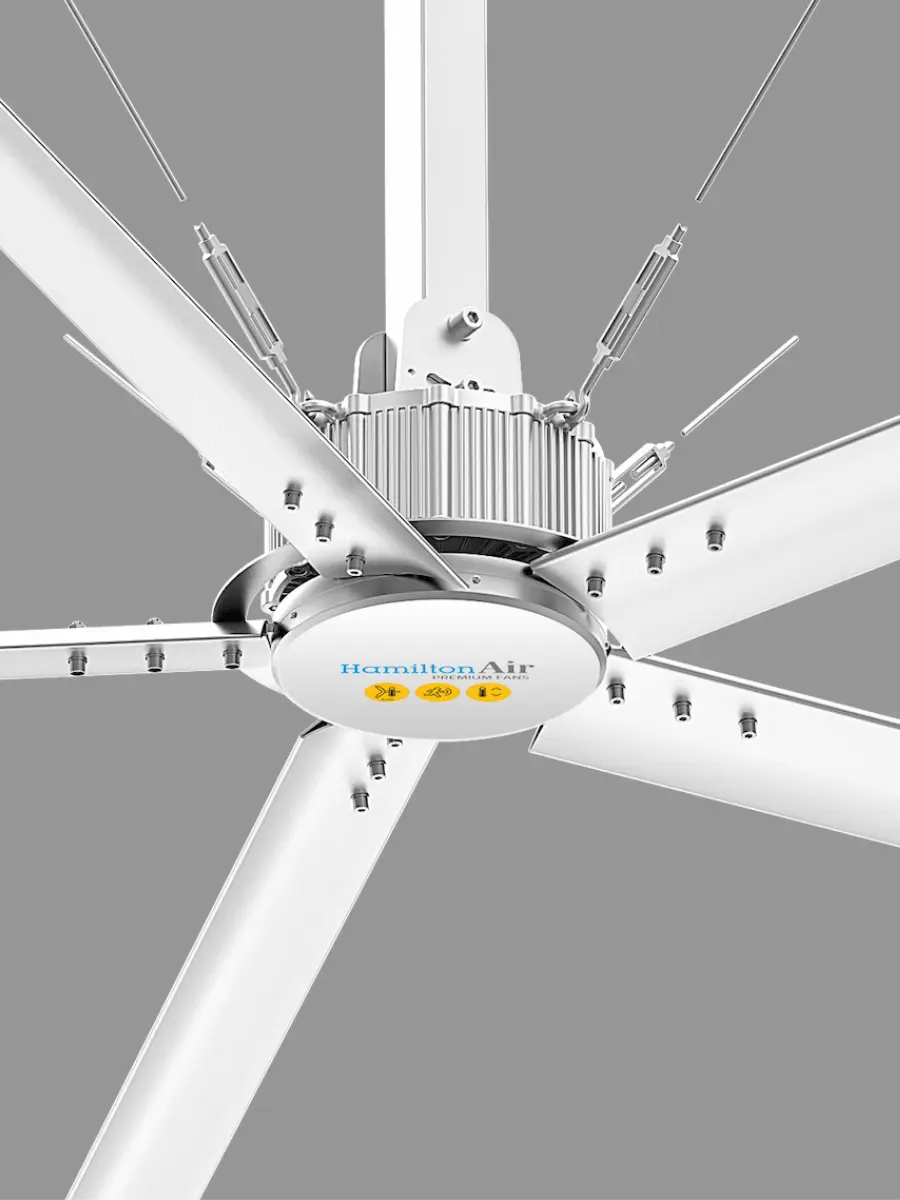
5-blade flagship HVLS fan with gearless PMSM motor. The workhorse of Hamilton Air's lineup — reliable, energy-efficient, and proven across hundreds of Vietnam factory and warehouse installations.
HERO-6 V380e
Next-generation 6-blade HVLS engineered for maximum airflow and maximum industrial protection. IP65 rated for dust-tight and water-jet environments.
HERO-8 ADF
8-blade ultra-high-output HVLS for mega facilities. Advanced Distributed Flow technology ensures even air distribution across enormous spans — stadiums, exhibition halls, mega warehouses.
Powersky X6
6-blade HVLS fan with BLDC motor, OLED digital control display, and smart controller. Ideal for logistics centers and modern distribution facilities.
Sunon Series 10
Premium Taiwan-engineered HVLS, diameter Ø5m–Ø7.3m. BLDC high-efficiency motor for low operating costs. Rigorous QC standards for industrial durability.
Sunon Series 3
Compact HVLS for mid-size facilities, ceiling heights 5–10m. Diameter range Ø2.5m–Ø4.3m. Right-sized for workshops, sports halls, and commercial spaces.
Pandora V180e
Flagship large ceiling fan for commercial architecture. 1.8m diameter delivers impressive airflow across open-plan commercial spaces, lobbies, and hospitality venues.
Pandora V150e
Premium commercial ceiling fan combining strong airflow with architectural-grade design. Ideal for showrooms, boutique hotels, restaurants, and high-end residential projects.
NOVA Series
Minimalist aerodynamic ceiling fan with clean architectural lines. NOVA's blade geometry is optimized for airflow efficiency while maintaining a visually light profile for modern interiors.
SUNON Powerful Series 1
Taiwan-engineered large ceiling fan for small to mid-size commercial spaces. BLDC motor delivers high efficiency and silent operation. Available Ø1.5m to Ø3m.
Pulsar II
European-engineered industrial directional fan built for continuous heavy-duty operation. Superior airflow output and durability for manufacturing environments running 24/7.
Syncro II
Italian industrial fan with advanced motor technology for low-vibration, low-noise operation. For continuous industrial environments where mechanical reliability is non-negotiable.
Post-Installation Maintenance Schedule
HVLS fans are designed for low-maintenance operation. Hamilton Air PMSM motors are sealed-for-life with no gearbox oil or brush replacement required. A simple periodic inspection schedule ensures maximum operational life.
| Interval | Task | Performed By | Notes |
|---|---|---|---|
| Monthly | Visual inspection — check for unusual vibration, noise, or visible damage | Facility staff | Run fan at low speed, observe from ground level. Report anomalies immediately. |
| 3 Months | Wipe down blade surfaces and motor housing to remove dust buildup | Facility staff | Use dry cloth. Do not apply water or solvents directly to motor. Lock out power first. |
| 6 Months | Torque check all accessible fasteners: blade arms, drop rod, mounting clamp | Qualified technician | Use calibrated torque wrench. Reference installation torque specs in manual. |
| 6 Months | Inspect safety cable, safety lanyard, and retention anchor points | Qualified technician | Replace any cable showing kinking, corrosion, or strand damage. Zero tolerance. |
| Annual | Full inspection: mounting, motor, blades, wiring, controller, airflow test | Hamilton Air service team | Required for warranty compliance. Includes commissioning certificate renewal. |
| 5 Years | Structural anchor assessment by qualified structural engineer | Structural engineer | Particularly important in coastal, high-humidity, or chemically aggressive environments. |
Frequently Asked Questions
Answers to the most common questions our engineers receive from project managers, procurement teams, and facility operators planning HVLS fan installations.
HVLS fans require a minimum ceiling height of 3.5m for smaller diameters (up to Ø3m). For large industrial HVLS fans with diameters of 5–7.3m, a minimum ceiling clearance of 6–9m is recommended to ensure an optimal downward airflow column and safe blade clearance above personnel and equipment. The effective "column" of air produced by a 7.3m fan extends 9–12m downward, so higher ceiling heights generally translate to wider floor coverage.
As a general rule, one HVLS fan covers approximately 1,000–2,000 m² of floor area, depending on diameter and ceiling height. For a 7.3m fan at 9m ceiling height, effective coverage can reach 1,800–2,000 m². Buildings with obstructions such as high racking, mezzanines, or process equipment may require closer spacing. Hamilton Air provides free CAD-based fan placement layouts for projects with 3 or more fans.
Most commercial HVLS fans operate on single-phase 220V or three-phase 380V power. PMSM and BLDC models typically draw 0.5–2.5 kW at full load. A dedicated circuit with appropriate breaker sizing (typically 16–32A) and proper grounding is required per TCVN 7447 (Vietnam's electrical installation standard). Larger fans (>Ø6m) generally require 3-phase supply.
Ready to Install?
Get a Free Site Assessment & HVLS Proposal
Hamilton Air's engineering team surveys your facility, designs the optimal fan layout, and delivers a full technical and commercial proposal — at no cost or obligation.


